Notes › ENGR 2334: Electric Circuits I Lecture 4
Methods of Analysis of Resistive Circuits
587 words 4 min Modified
Table of Contents
Nodal Analysis
- A method to obtain element and node voltages in a circuit
- One node is the reference node, which supplies GND and is taken to be 0 V
- For $n$ nodes, there are $n-1$ nodal equations
Procedure
- Choose a good reference node location
- Draw the nodes for the locations you want to find
- Express the voltage of each circuit element in terms of two node voltages
- Which is just $\Delta v = v_{1} - v_{2}$, assuming the circuit element lies between $v_1$ and $v_2$
- Rewrite this expression for current ($i = GV$ or $i = \frac{\Delta v}{R}$) using Ohm’s Law
- Apply Current Law to each node (excluding reference node)
- Solve the system of linear equations for each node voltage via substitution
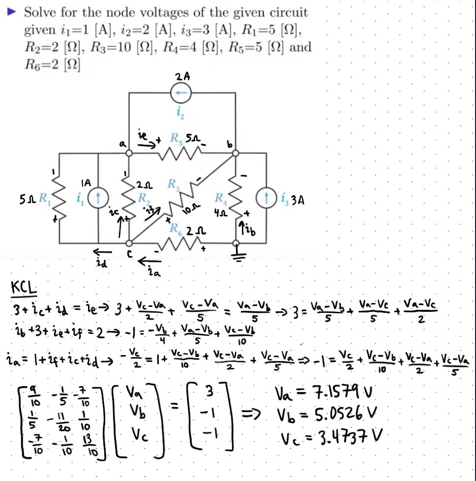
Example
Independent Voltage Sources
- Adding a voltage source adds a voltage constraint to the system (one less KCL equation needed)
- Nodes directly in front of a voltage source have the same nodal voltage as that voltage source
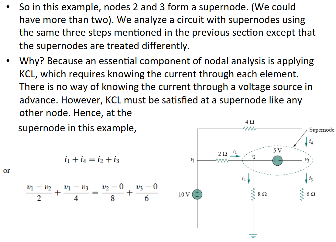
Supernodes
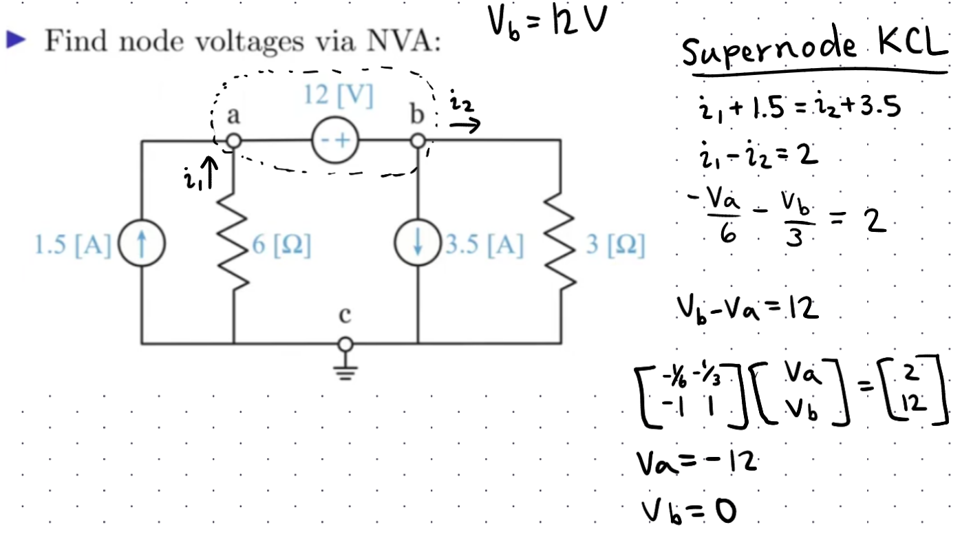
- If there exists a voltage source between two nodes, then they combine to form a supernode
- The supernode may be analyzed with KCL like normal reference nodes
- However, the sum of the currents entering both reference nodes must equal the sum of the currents exiting both reference nodes
Example
Voltage Source Equation
- Recall that voltages in series can be added together
- Therefore, the final voltage in a series of unknown voltages will equal the sum of voltages that came become it.
- This is generalizable for any voltage source between two reference nodes; in the diagram below, $V_1 = V_2 + V_A$:
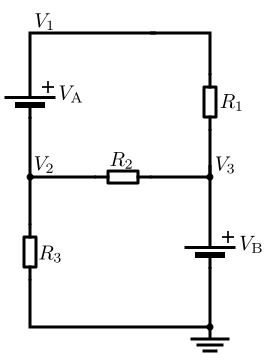
- This is generalizable for any voltage source between two reference nodes; in the diagram below, $V_1 = V_2 + V_A$:
- The resulting equation is known as the constraint equation
Dependent Voltage Sources
-
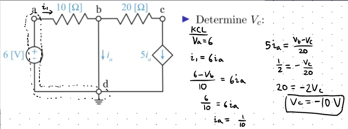
When a dependent (or controlled) current or voltage source is present, an additional equation is needed to express the controlling variable in terms of node voltages
- If the dependent source is a current source, include it directly in the current matrix ($\mathbf{i}$)
- If the dependent source is a voltage source, it either:
- Creates a supernode, requiring an extra equation
- Adds a constraint equation relating node voltages
Example
Matrix Method
- It is possible to solve for voltages directly by inspection using a conductance matrix
- For $n$ nodes, you will have an $n \times n$ symmetrical conductance matrix that is laid as follows:
or simply $\mathbf {Gv} =\mathbf {i}$, where: - G is the conductance matrix, constructed as: - Diagonal elements $G_{kk}$ are the sum of conductances connected to node $k$ - Off-diagonal elements $G_{kj}$ are the negative conductance between nodes $k$ and $j$ - $\mathbf{v}$ is the vector of unknown node voltages - $\mathbf{i}$ is the vector of known current injections at each node
- Thus, the final solution is $\mathbf{v}=\mathbf{G}^{-1}\mathbf{i}$
- Cannot be used when there is a voltage constraint or supernode; therefore, only good when there are independent current sources
Mesh Analysis
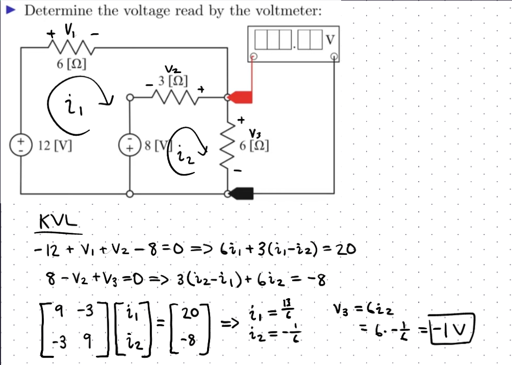
- A mesh is a loop that has no loops within it
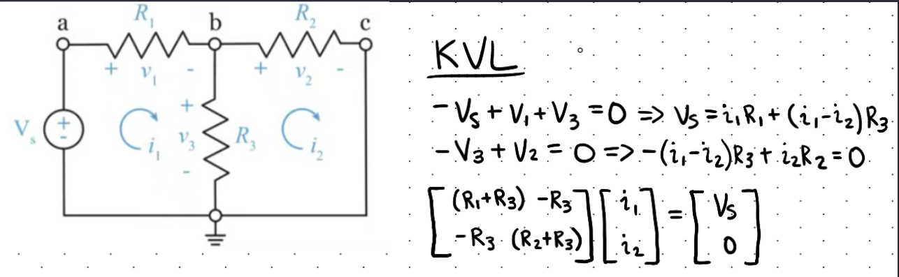
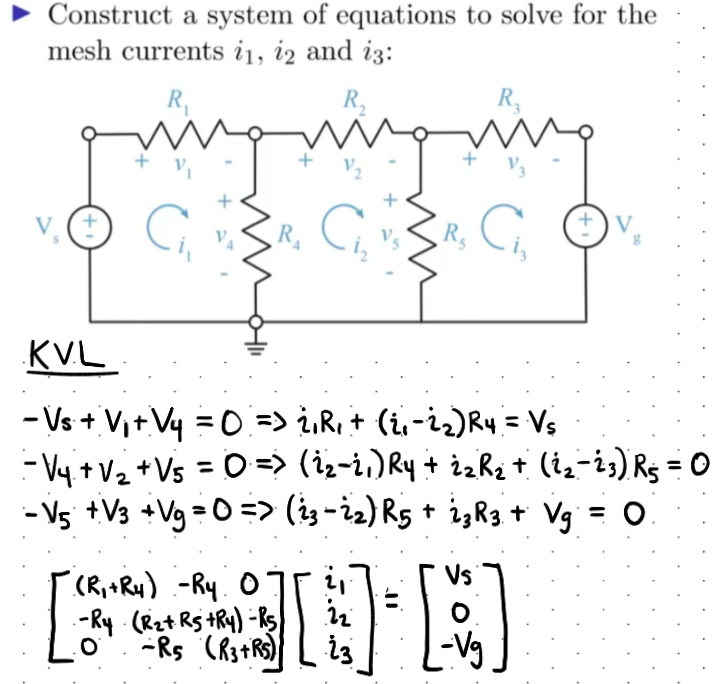
- For $N$ meshes, we write $N$ KVL equations
- Write voltage drops in terms of mesh currents and resistances
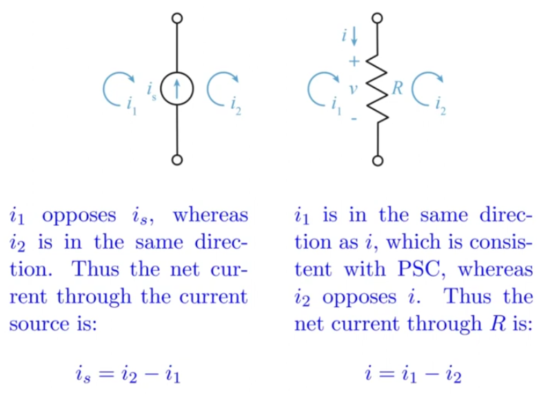
Shared Loop Currents
Examples
Independent Current Sources
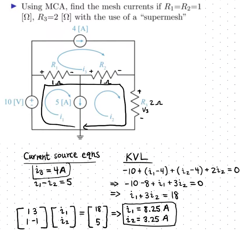
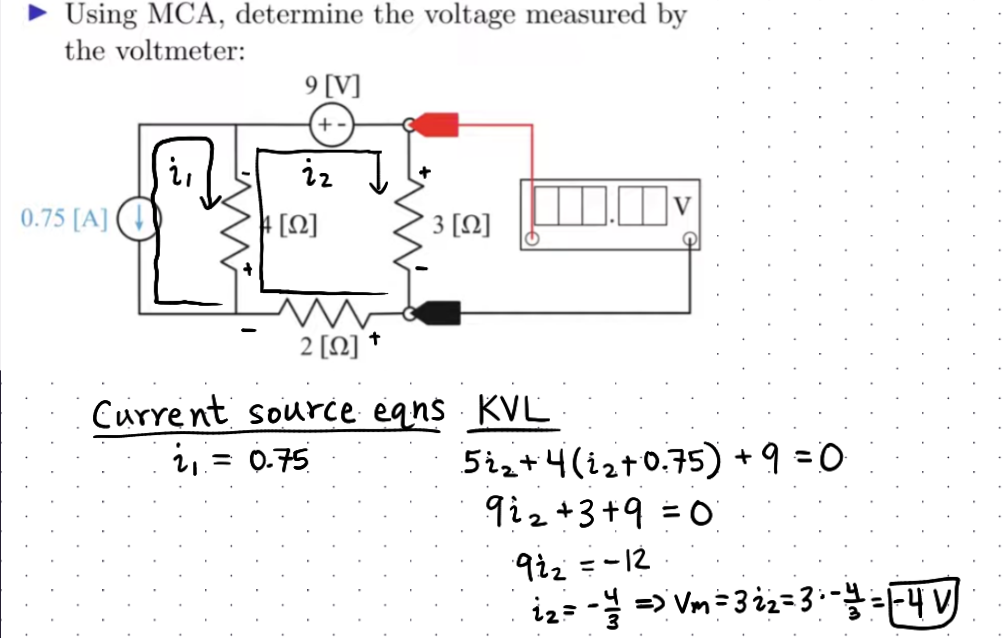
- For $N_c$ current sources, you have $N_c$ current equations relating the current source to 1 or more mesh currents
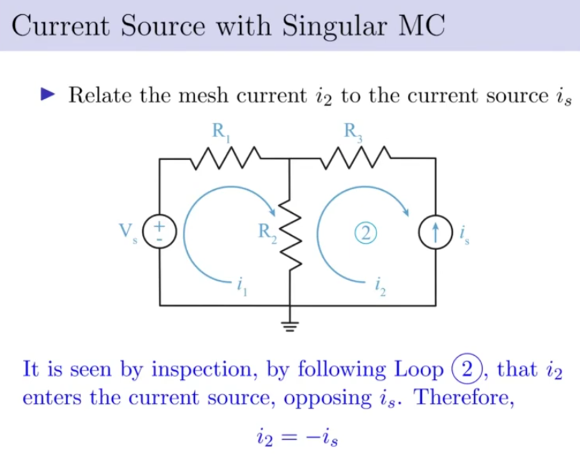
Supermeshes
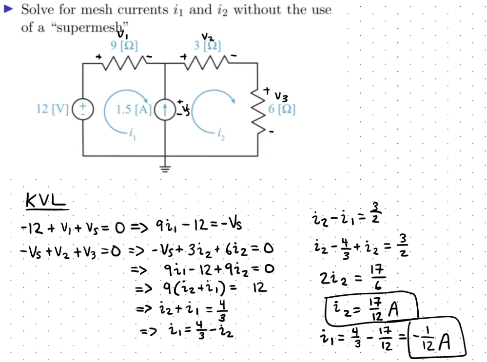
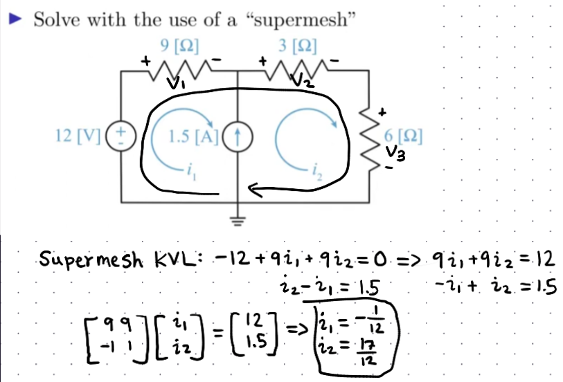
- If there exists a current source between two mesh currents, you have to construct a supermesh
- Total equations: $N-N_c$
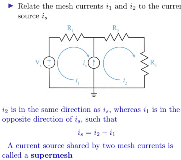
Examples
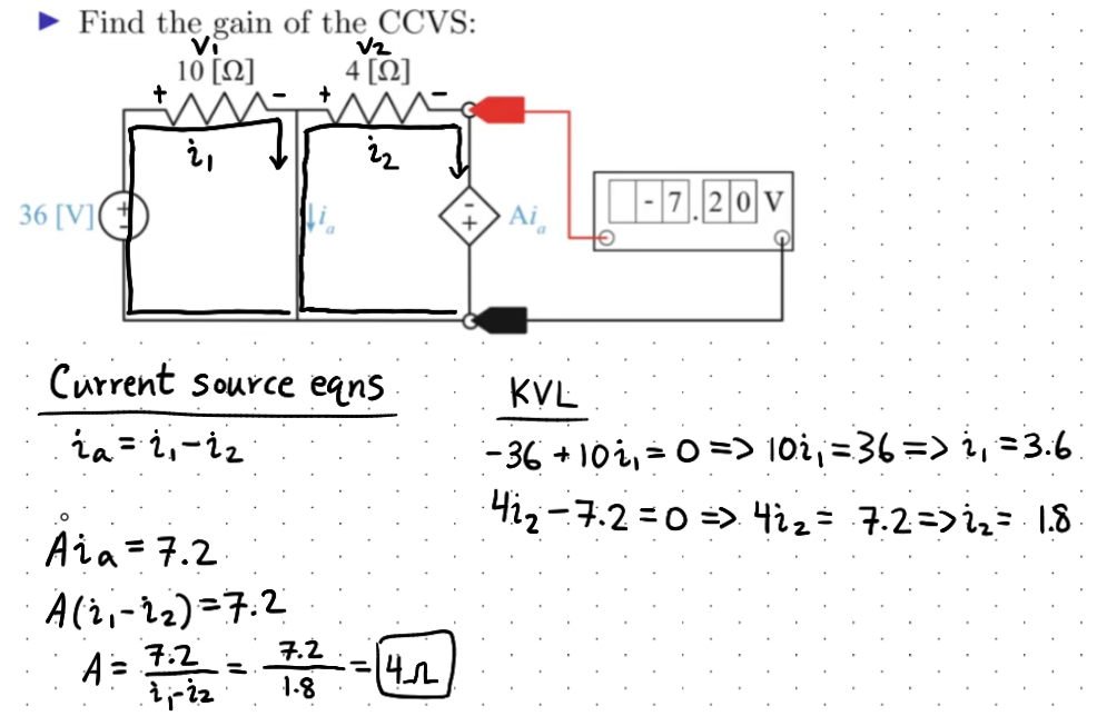
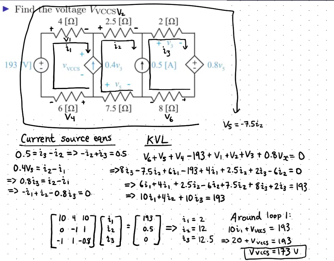
Dependent Current Sources
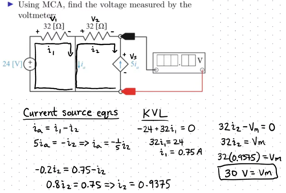
- Write the dependent source value in terms of the mesh currents
- Total equations: $N-N_c$ for $N_c$ sources
Examples
References
- Nodal analysis
- Mesh analysis
- Course slides, chapter 4: Methods of Analysis of Resistive Circuits
Sources
- Course slides, chapter 4: Methods of Analysis of Resistive Circuits