Notes › Fundamentals of Electric Circuits (Sadiku) Lecture 3
Methods of Analysis
938 words 7 min Modified
Table of Contents
Nodal Analysis
- A procedure for analyzing circuits using node voltages as variables
- It’s better to use node voltages instead of circuit elements because it reduces the number of equations
- Goal is to determine the node voltages using KCL, which are defined to be positive wrt ground
- Steps:
- Assign a ground node with $v = 0$ and $v_{i}$ for the remaining $n-1$ nodes
- Apply KCL to each $n-1$ nonreference node. Express the currents in terms of the node voltages
- Solve the resultant system
- Since current flows from a higher to lower potential in a resistor, the current is
(Practice Problem 3.1
[Alexander & Sadiku, Fundamentals of Electric Circuits, 7th ed., p. 109])
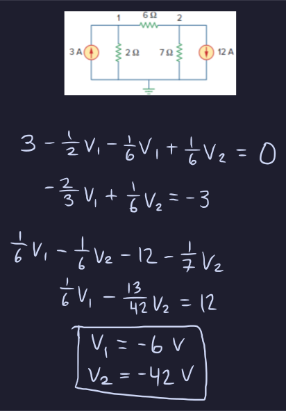
(Practice Problem 3.2
[Alexander & Sadiku, Fundamentals of Electric Circuits, 7th ed., p. 112])
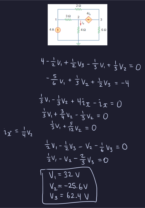
Nodal Analysis with Voltage Sources
- When dealing with voltage sources, we must examine two cases:
- The voltage source is between ground and a nonreference node. Then, the voltage at the nonreference node is equal to the voltage of the voltage source
- The voltage source is between two nonreference nodes. Then, the two nodes form a supernode, and we must apply both KCL and KVL to determine the node voltages
Formed by enclosing a voltage source connected between two nonreference nodes and any elements connected in parallel with it. Has the following properties:
- The enclosed voltage source provides a constraint equation, which is derived using KVL
- Has no voltage of its own
- Requires both KCL and KVL
(Practice Problem 3.3
[Alexander & Sadiku, Fundamentals of Electric Circuits, 7th ed., p. 114])
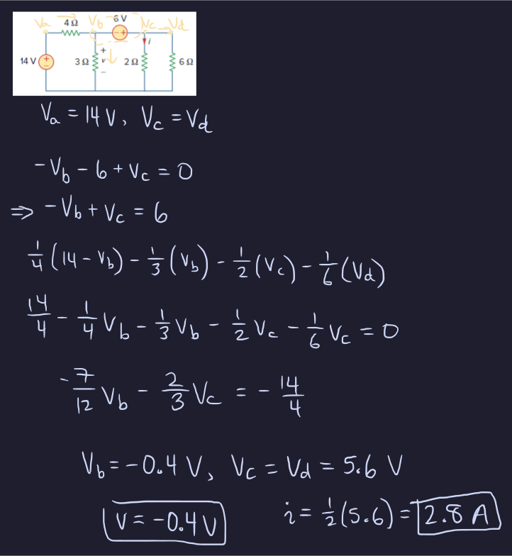
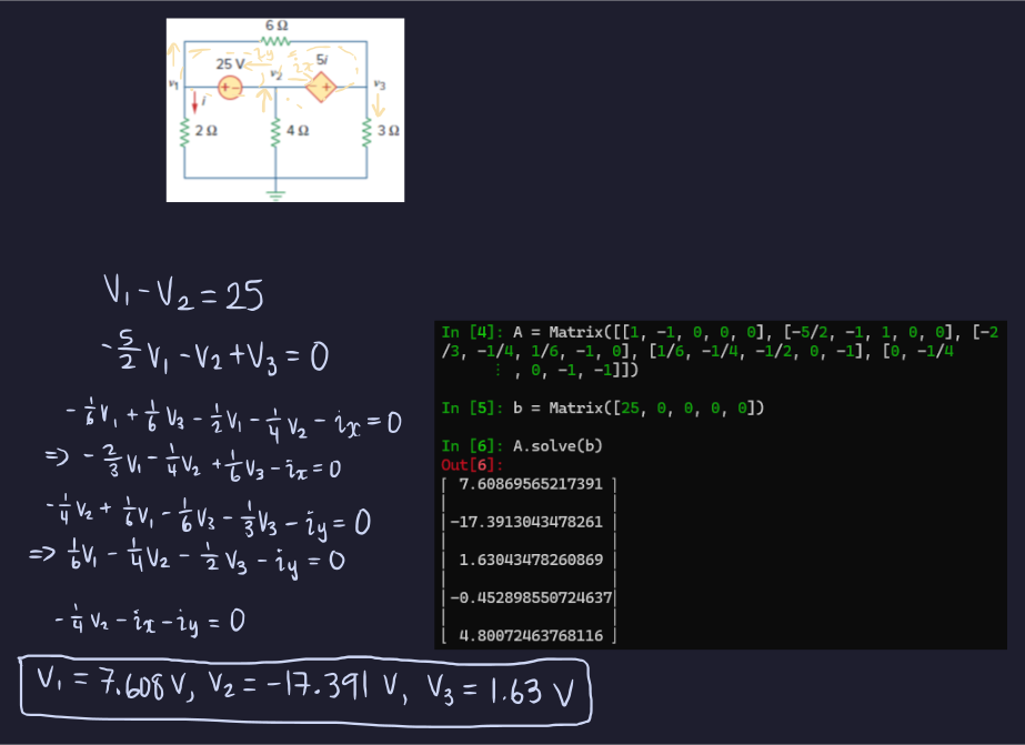
(Practice Problem 3.4
[Alexander & Sadiku, Fundamentals of Electric Circuits, 7th ed., p. 117])
Mesh Analysis
- Use KVL to find unknown currents using mesh currents as circuit variables
- A mesh is a loop that does not contain any other loop within it
- Only applicable to planar circuits (no branches crossing one another)
- Steps:
- Assign mesh currents $i_{i}$ to the $n$ meshes
- Apply KVL to each mesh. Express the voltages in terms of the mesh currents
- Solve the resultant system
- For each KVL equation:
- The coefficient of the mesh current being solved is positive and equal to the sum of all resistances in the mesh
- The coefficient of any adjacent mesh current is the negative of the sum of resistances shared between the mesh and the shared mesh
- All voltage rises may be summed and written on the RHS (i.e., voltage sources)
- Use capital $I$ for branch currents and lowercase $i$ for mesh currents
(Practice Problem 3.5
[Alexander & Sadiku, Fundamentals of Electric Circuits, 7th ed., p. 120])
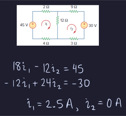
(Practice Problem 3.6
[Alexander & Sadiku, Fundamentals of Electric Circuits, 7th ed., p. 122])
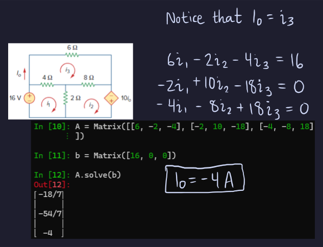
Mesh Analysis with Current Sources
- When dealing with current sources, we must examine two cases:
- The current source is exclusive to one mesh. Then, the mesh current is equal to the current source
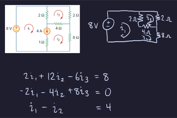
- The current source is shared between two meshes. Then, the two meshes form a supermesh by excluding the branch with the current node and any elements in series with it. Perform KVL on the supermesh and apply KCL to a node where the two meshes intersect
Results when two meshes have a current source in common. Has the following properties:
- The current source provides a constraint equation for the mesh currents using KCL
- Has no current of its own
- Requires both KVL and KCL
(Practice Problem 3.7
[Alexander & Sadiku, Fundamentals of Electric Circuits, 7th ed., p. 124])
Analysis by Inspection
Nodal Analysis by Inspection
- KCL not needed if all the sources are independent current sources; the resulting system is $$\mathbf{Gv = i}$$with $\mathbf{G}$ being the conductance matrix, $\mathbf{v}$ being the output vector, and $\mathbf{i}$ being the current matrix/input vector
- For the conductance matrix:
- The $i$th diagonal term is the sum of the conductances in branches connected to the $i$th node
- The off-diagonal terms are the negatives of the sum of the conductance in the branches connected between two nodes $i$ and $j$
- For the current matrix:
- The $n$th term is the sum of the currents entering the $n$th node
- If a circuit with independent current sources has $N$ nonreference nodes, the system in terms of the conductances is:
- Shortcut: there is symmetry along the diagonal, so all the off-diagonals across from one another should be equal
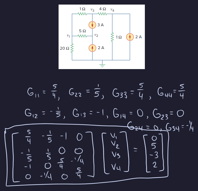
(Practice Problem 3.8
[Alexander & Sadiku, Fundamentals of Electric Circuits, 7th ed., p. 127])
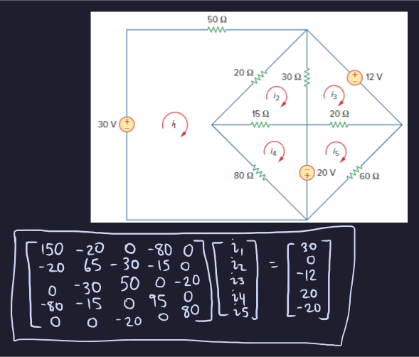
Mesh Analysis by Inspection
- Matrix is of the form
$$\mathbf{Ri = v}$$where:
- $R_{ii}$ = Sum of resistances in mesh $i$
- $R_{ij} = R_{ji} =$ Negative of sum of resistances in common with meshes $i$ and $j$
- $i_{N}$ = Unknown mesh current up to the $N$th mesh
- $v_{N}$ = Sum of all independent voltage sources up to the $N$th mesh
- Thus, the generalized matrix is:
$$ \begin{bmatrix} R_{11} & R_{12} & \dots & R_{1j} \ R_{21} & R_{22} & \dots & R_{2j} \ \vdots & \vdots & \ddots & \vdots \ R_{i1} & R_{i2} & \dots & R_{ij} \end{bmatrix} \begin{bmatrix} i_1 \ i_2 \ \vdots \ i_N \end{bmatrix}
\begin{bmatrix} v_1 \ v_2 \ \vdots \ v_N \end{bmatrix} $$
(Practice Problem 3.9
[Alexander & Sadiku, Fundamentals of Electric Circuits, 7th ed., p. 128])
Sources
- Alexander & Sadiku, Fundamentals of Electric Circuits