Notes › Fundamentals of Electric Circuits (Sadiku) Lecture 2
Basic Laws
1558 words 12 min Modified
Table of Contents
Resistance and Ohm’s Law
Resistance
Resistance is the behavior of a material to resist the flow of electric charge, represented by
where $\rho$ is the resistivity in $\Omega m$, $\ell$ is length, and $A$ is cross-sectional area.
Resistivities of Common Materials
| Material | Resistivity (Ω·m) | Usage |
|---|---|---|
| Silver | 1.64 × 10⁻⁸ | Conductor |
| Copper | 1.72 × 10⁻⁸ | Conductor |
| Aluminum | 2.8 × 10⁻⁸ | Conductor |
| Gold | 2.45 × 10⁻⁸ | Conductor |
| Carbon | 4 × 10⁻⁵ | Semiconductor |
| Germanium | 47 × 10⁻² | Semiconductor |
| Silicon | 6.4 × 10² | Semiconductor |
| Paper | 10¹⁰ | Insulator |
| Mica | 5 × 10¹¹ | Insulator |
| Glass | 10¹² | Insulator |
| Teflon | 3 × 10¹² | Insulator |
The Resistor
- The simplest passive element
- Used to model the current-resisting behavior of a material
- $R$ is the resistance of the resistor
Types of Resistors
- Fixed resistors have constant $R$
- Variable resistors, such as potentiometers, have adjustable $R$
Ohm’s Law
The voltage $v$ across a resistor is directly proportional to the current $i$ through the resistor.
$$v \propto i$$The proportionality constant for this relationship is the resistance, $R$. So, the equation becomes
$$v = iR.$$- To obey the passive convention, the current direction and voltage polarity must flow from a high potential (VCC) to low potential (GND)
- Since $R \in [0, \infty]$, we must consider two extremal values of $R$:
- When $R = 0$, there is a short circuit; the voltage is zero but the current can be anything
- When $R = \infty$, there is an open circuit; the current is zero but the voltage can be anything
Any circuit element with $R \rightarrow 0$. In practice, this is a connecting wire between two points in the circuit, in which the charge carriers take the path of least resistance.
Any circuit element with $R \rightarrow \infty$. In practice, this is a literal gap in the circuit, since air is a perfect insulator.
Conductance
The ability of an element to conduct electric current; it is measured in mhos ($\mho$)/siemens (S).
- Ohm’s Law under conductance may be expressed as:
Power Dissipated by a Resistor
- Nonlinear in terms of current or voltage
- Can be expressed in terms of $R$:
- Or in terms of $G$:
- Since $R$ and $G$ are always positive, power dissipated is always positive; therefore, resistors always absorb power (adheres to the passive convention)
(Practice Problem 2.1
[Alexander & Sadiku, Fundamentals of Electric Circuits, 7th ed., p. 60])
1In [1]: eq = Eq(110**2 / 15, x * 110)
2
3In [2]: solve(eq, x)
4Out[2]: [7.33333333333334](Practice Problem 2.2
[Alexander & Sadiku, Fundamentals of Electric Circuits, 7th ed., p. 61])
1In [1]: v = 3e-3 * 10e3
2
3In [2]: G = 1/10e3
4
5In [3]: p = 3e-3**2 * 10e3
6
7In [4]: v, G, p
8Out[4]: (30.0, 0.0001, 0.09)(Practice Problem 2.3
[Alexander & Sadiku, Fundamentals of Electric Circuits, 7th ed., p. 61])
 1In [2]: p = 30*cos(t)**2
 2
 3In [3]: v = 15*cos(t)
 4
 5In [4]: i = p / v
 6
 7In [5]: R = v**2 / p
 8
 9In [6]: i, R
10Out[6]: (2⋅cos(t), 15/2)
Nodes, Branches, and Loops
Any two-terminal element in a circuit, such as a power source or resistor. The number of branches equals the number of circuit elements.
The point of connection between two or more branches.
- Typically indicated by a dot in a circuit
- If a short circuit connects two nodes, the two nodes may be treated as a single node
Any closed path in a circuit.
- A “closed path” starts at a node, passes through a set of nodes, and returns to the starting node without passing through any node more than once.
- Is independent if it contains a branch that is not part of any other independent loop
- Independent loops result in independent sets of equations
- A network with $b$ branches, $n$ nodes, and $l$ independent loops will satisfy the following relation (The Fundamental Theorem of Network Topology):
- Two elements are in series if they exclusively share a single node
- Consequently, they share the same current
- Two elements are in parallel if they are connected to the same two nodes
- Consequently, they share the same voltage
(Practice Problem 2.4
[Alexander & Sadiku, Fundamentals of Electric Circuits, 7th ed., p. 63])
- 5 elements, so 5 branches
- 3 nodes
- 4 $\Omega$ is in parallel with 10V
- 1 $\Omega$ is in parallel with 2 $\Omega$
Kirchoff’s Laws
Kirchoff’s Current Law
- Based on the principle of conservation of charge
The algebraic sum of currents entering/exiting a node is zero.
$$ \sum_{n=1}^{N} i_{n} = 0 $$where $N$ is the number of branches connected to the node and $i_{n}$ is the $n$th current entering/exiting the node.
- Currents entering a node is positive, while leaving current is negative
- Alternative interpretation: the sum of currents entering a node is equal to the sum of the currents leaving the node
- KCL may also be applied to any closed boundary, since a node is a closed surface shrunk to a point
- A consequence of KCL is that a circuit cannot contain two different currents in series
- Another consequence is that current sources in parallel may be added together
Kirchoff’s Voltage Law
- Based on the principle of conservation of energy
The algebraic sum of all voltages around a loop is zero.
$$ \sum_{m = 1}^{M} v_{m} = 0 $$where $M$ is the number of branches in the loop and $v_{m}$ is the $m$th voltage.
- Can go clockwise or counterclockwise around the loop
- The sign on each voltage is the polarity of the terminal encountered first
- Alternative interpretation: the sum of voltage drops is equal to the sum of voltage rises
- A consequence of KVL is that a circuit cannot contain two different voltages in parallel
- Another consequence is that voltage sources in series may be added together
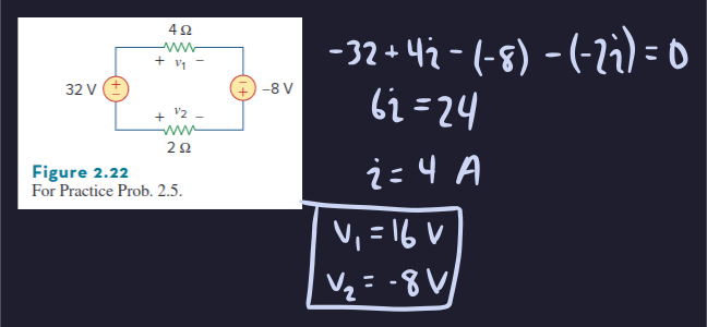
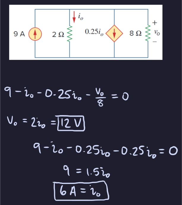
(Practice Problem 2.5
[Alexander & Sadiku, Fundamentals of Electric Circuits, 7th ed., p. 67])
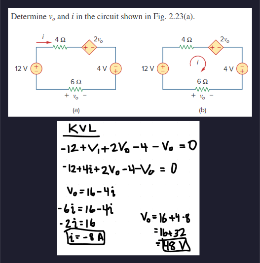
(Example 2.6
[Alexander & Sadiku, Fundamentals of Electric Circuits, 7th ed., p. 67])
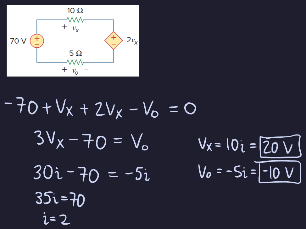
(Practice Problem 2.6
[Alexander & Sadiku, Fundamentals of Electric Circuits, 7th ed., p. 67])
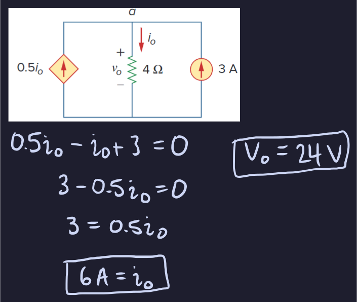
(Example 2.7
[Alexander & Sadiku, Fundamentals of Electric Circuits, 7th ed., p. 68])
(Practice Problem 2.7
[Alexander & Sadiku, Fundamentals of Electric Circuits, 7th ed., p. 68])
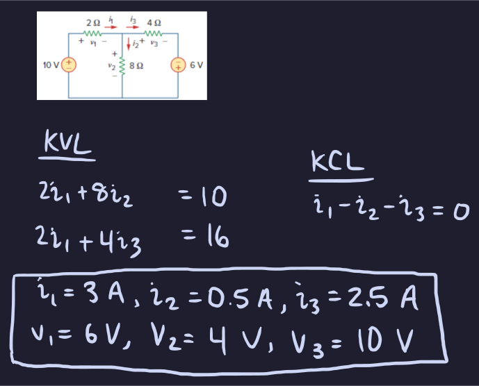
(Practice Problem 2.8
[Alexander & Sadiku, Fundamentals of Electric Circuits, 7th ed., p. 69])
Series Resistance
The equivalent resistance $R_{\text{eq}}$ of any number of resistors connected in series is the sum of the individual resistances.
$$R_{\text{eq}} = \sum_{n=1}^{N} R_{n}$$- Series resistors share the same current, but not the same voltage
- However, the total voltage across all the resistors (the equivalent resistor) can be calculated as $R_{\text{eq}} i$
Voltage Division
- A voltage source connected to a network of resistors in series effectively divides up that voltage, known as a voltage divider
- The resistance of the $n$th resistor in the voltage divider is calculated as:
Parallel Resistances
The equivalent resistance of two parallel resistors is equal to the product of their resistances divided by their sum.
$$R_{\text{eq}} = \frac{R_{1}R_{2}}{R_{1}+R_{2}}$$For $n$ resistors in parallel, the equivalent resistance is
$$R_{\text{eq}} = \left(\sum_{n=1}^{N} \frac{1}{R_{n}}\right)^{-1}.$$- $R_{\text{eq}}$ is always less than the smallest resistor in parallel
- If all the resistances in the parallel network are the same, then:
Equivalent Conductance
- Since $G = \frac{1}{R}$ by definition, it is possible to express parallel resistance in terms of conductance:
where $G_{\text{eq}}$ = $\frac{1}{R_{\text{eq}}}$
- The same may be done for series resistance:
Current Division
- The total current in a network of parallel elements is effectively divided across those elements, known as current division
- The current of the $n$th resistor in the current divider is calculated as:
or using the conductance definition:
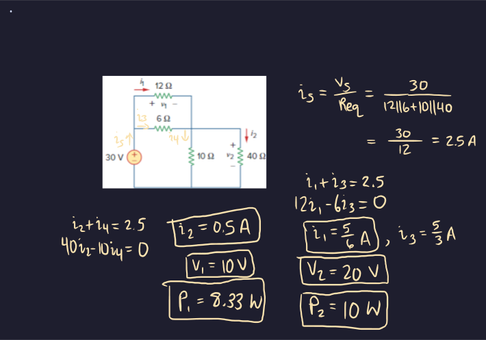
$$i_{n} = \frac{i_{s}G_{n}}{G_{\text{eq}}}$$(Practice Problem 2.12
[Alexander & Sadiku, Fundamentals of Electric Circuits, 7th ed., p. 76])
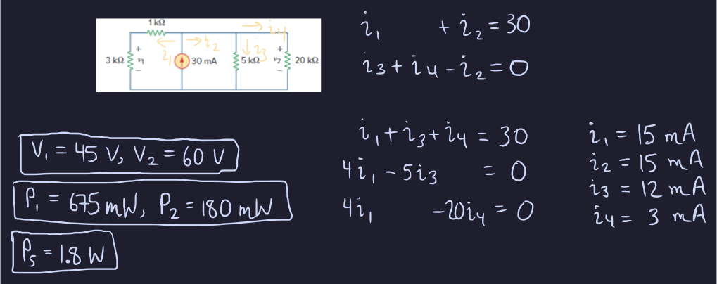
(Practice Problem 2.13
[Alexander & Sadiku, Fundamentals of Electric Circuits, 7th ed., p. 77])
Wye-Delta Transformations
- Resistive networks that aren’t in series or parallel may be simplified to a three-terminal equivalent network
- Either the Wye/Tee network or the Delta/Pi network
Delta-Wye Conversion
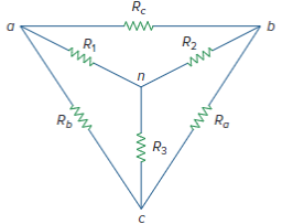
- Superimpose Y onto $\Delta$ by adding an extra node $n$. Each resistor in Y is the product of the resistors in the two adjacent $\Delta$ branches divided by the sum of the three $\Delta$ resistors
- For the network below:
Wye-Delta Conversion
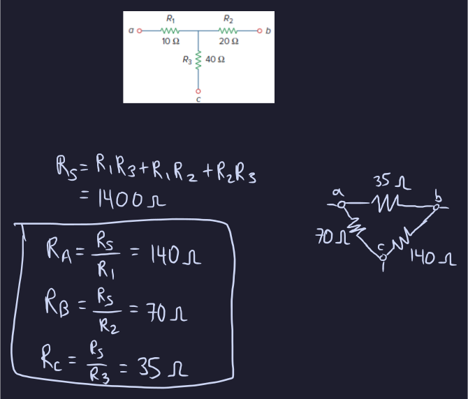
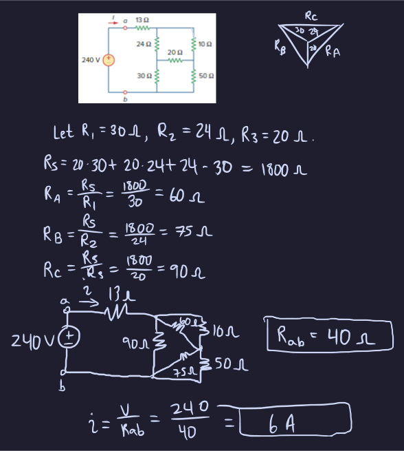
- Each resistor in the $\Delta$ network is the sum of all products of Y resistors divided by the opposite Y resistor
- For the superimposed network:
Balanced Condition
- If all the Y resistances are equal AND all the $\Delta$ resistances are equal, then:
(Practice Problem 2.14
[Alexander & Sadiku, Fundamentals of Electric Circuits, 7th ed., p. 80])
(Practice Problem 2.15
[Alexander & Sadiku, Fundamentals of Electric Circuits, 7th ed., p. 83])
Sources
- Alexander & Sadiku, Fundamentals of Electric Circuits