Notes › EENG 3345: AC Circuit Analysis Lecture 5
AC Steady State Power, Mutual Inductance, Ideal Transformer
610 words 4 min Modified
Table of Contents
RMS and Average Quantities
- For $v(t)$ and $i(t)$ we use RMS; for $p(t)$, we use average
- For purely resistive loads, $p_{\text{avg}} = V_{\text{rms}} I_{\text{rms}}$
- For purely reactive loads (inductor/capacitor), $p_{\text{avg}} = 0$
- $\phi$ is the phase between V and I
Types of Electric Power
- ALWAYS USE RMS VALUES FOR CURRENT AND VOLTAGE OR YOU WILL GET THE QUESTION WRONG!
- Real/Active Power $(P)$: Actual power consumed, measured in watts (W)
- Reactive Power $(Q)$: Power stored/released by inductors and capacitors, measured in Volt-Amps-Reactive (VAR)
- Apparent Power $(|S|)$: Combination of reactive power and true power, measured in Volt-Amps (VA)
- Magnitude of complex power, $S$
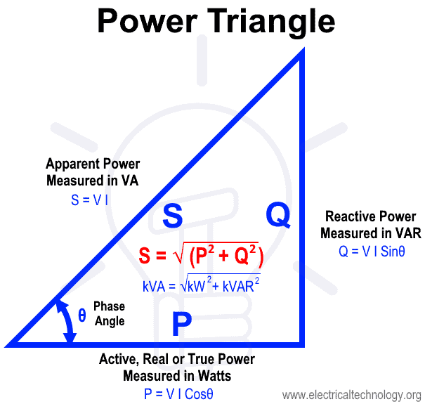
Complex Power
- Shows the total power running through the AC circuit, measured in Volt-Amps
Power Factor
- Ratio of real power to apparent power
- Shows how effectively electrical power is being used
Mutual Inductance
-
The property of two coils or inductors that enables energy transfer through a shared magnetic field
-
When the current in one coil changes, it generates a time-varying magnetic field that links with the second coil, inducing an emf
-
Dependent on
- The number of turns in each coil
- The core material (permeability)
- The geometrical arrangement of the coils
- The degree of magnetic coupling
-
Magnetic flux linkage definition:
Where:
-
$M$ is the mutual inductance in Henries (H)
-
$\Phi_{21}$ is the magnetic flux in coil 2 due to current in coil 1
-
$\Phi_{12}$ is the magnetic flux in coil 1 due to current in coil 2
-
$N_1, N_2$ are the number of turns in coils 1 and 2
-
$I_1, I_2$ are the respective coil currents
-
Induced voltage in coil 1 from changing current in coil 2:
- Induced voltage in coil 2 from changing current in coil 1:
-
When the two coils are part of the same circuit, the mutual inductance also affects the total voltage across each inductor
-
Voltage across the first inductor:
- Voltage across the second inductor:
- The sign depends on the relative orientation of the coils, determined by the dot convention
- A positive sign is used if current enters the dotted terminal of both coils and negative otherwise
Ideal Transformer
-
Theoretical device that models perfect magnetic coupling between two coils to step up or step down voltage/current while maintaining constant apparent power. It assumes:
- No energy losses (no winding resistance, no core losses)
- Perfect magnetic coupling (coupling coefficient $k = 1$)
- All magnetic flux produced by the primary winding links with the secondary winding
- Infinite core permeability (zero magnetizing current)
-
An ideal transformer is used to:
- Match impedances
- Change voltage levels between circuits
- Isolate different parts of a system electrically
-
Turns ratio definition:
Where $a$ is the turns ratio (primary to secondary).
- Voltage transformation:
- Current transformation:
- Conservation of power:
(Example 13.1
[Alexander & Sadiku, Fundamentals of Electric Circuits, 7th ed., p. 585])
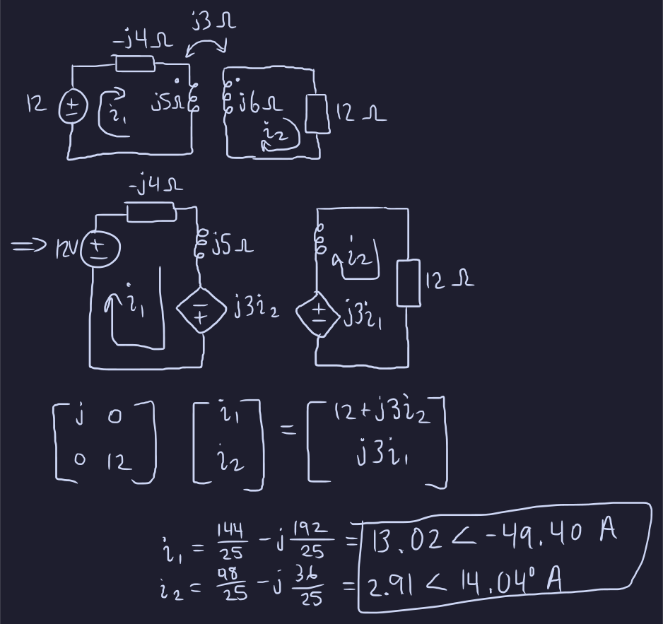
(From Quiz 3 - Ch11)
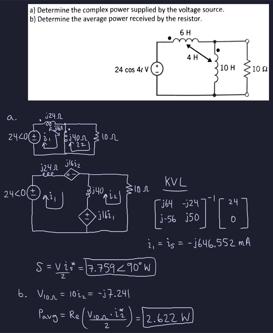
References
- AC Steady-State Power, Mutual Inductance, and (course handout)
Sources
- AC Steady-State Power, Mutual Inductance, and
- Alexander & Sadiku, Fundamentals of Electric Circuits