Notes › EENG 3341: Microelectronics Lecture 7
Bipolar Junction Transistors
226 words 1 min Modified
Table of Contents
Structure and Symbols
- Three terminals emitter base collector
- Types NPN PNP
- Emitter heavily doped
- Base thin and lightly doped
- Collector moderately doped larger area
- Arrow shows emitter conventional current for NPN out for PNP in
- Two pn junctions in series view
Currents and Voltages
- Define $i_E, i_B, i_C$ with $i_E = i_B + i_C$
- Node voltages $v_{BE} v_{BC} v_{CE}$
- Sign convention currents enter device terminals
Core Exponential Law
$$i_C = I_S e^{\frac{v_{BE}}{V_T}}$$- $V_T \approx 25\,\text{mV}$ at $300\,\text{K}$
- $I_S$ set by device geometry and temperature
Current Gain Relations
- Common emitter gain $\beta_F = \frac{i_C}{i_B}$
- Common base gain $\alpha_F = \frac{i_C}{i_E} = \frac{\beta_F}{\beta_F + 1}$:
Operating Regions
-
Cutoff: Open Circuit in branches BE and CE
- Condition when evaluating forward-active model: $i_B < 0$
- $v_{BE} < 0.7$
- $i_B = 0$ and $i_C = 0$
-
Saturation: No current amplification; constant potential difference at the junctions
- Condition when evaluating forward-active model (assuming $i_B > 0$): $V_{CE} \le 0.2$
- $V_{BE} = 0.7$
- $V_{CE} = 0.2$
-
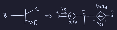
Forward active: Current is amplified
- Condition when evaluating forward-active model (assuming $i_B > 0$): $V_{CE} \gt 0.2$
- $V_{BE} = 0.7$
- $i_C \approx \beta_F i_B$
Common Emitter Output Behavior
- Plot $i_C$ versus $v_{CE}$ for fixed $i_B$
- Flat $i_C$ in forward active for $v_{CE}$ above a knee
- $i_B = 0$ gives cutoff curve
References
- Course slides, chapter 5: Bipolar Junction Transistors
Sources
- Course slides, chapter 5: Bipolar Junction Transistors