Notes › EENG 3341: Microelectronics Lecture 3
Solid-State Diodes and Diode Circuits
349 words 2 min Modified
Table of Contents
Diode
- Circuit element that only permits current in one direction
- Turn-on voltage is ~0.7 V at room temp
Diode Current
Definition 03.1 (The Diode Equation).
$$i_{D} = I_{S}\left[ \exp \left(\frac{q v_{S}}{nkT} \right) - 1 \right] = I_{S} \left[ \exp \left( \frac{v_{S}}{n V_{T}} \right) \right]$$
where:
- $I_S$ = reverse saturation current (A)
- $v_S$ = voltage applied to diode (V)
- $q$ = fundamental charge unit (1.602e-19 C)
- $k$ = Boltzmann constant (1.38e-23 J/K)
- $T$ = absolute temperature (K)
- $n$ = non-ideality factor (dimensionless, usually assumed to be 1)
- $V_T$ = kT/q = thermal voltage (V) (25 mV at room temp)
Diode Modes
- Reverse bias
- $V_D < 0$
- $i_{D} \approx -I_S$
- Zero bias
- $V_D = 0$
- $i_{D} \approx 0$
- Forward bias
- $V_D = 0$
- $i_{D} \approx I_S \exp \left( \frac{v_{D}}{nV_{T}} \right)$
Reverse Breakdown
- $i_D$ sharply increases with enough negative voltage in the reverse direction
- This is called the breakdown voltage, $V_Z$
Avalanche Breakdown
- As the E-field increases, the energy of charge carriers cause ionization of atoms, which turn into charge carriers and cause a positive feedback loop
- $V_Z$ = -5.6 V in normal silicon diodes
Zener Breakdown
- The E-field is strong enough to tunnel electrons from covalent bonds through the depletion region
- Occurs at higher voltages than avalanche
- Allows for voltage regulation, since $V_D$
Diode DC Analysis
- Find the quiescent operating point $(I_D, V_D)$ for the diode
- KVL equation characterizing diode behavior is known as the load line
- Many methods to find the load line
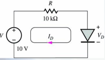
Load-Line Method
- Q-point is the graphical intersection of IV curve and load line
Mathematical Model
- Numerically solve for Q-Point using Diode Equation and Load-Line
Ideal Model
- Diode is a perfect switch when $v_S > 0.7$
- Unrealistic because the existence of a potential barrier implies that diodes must have a potential difference
- Useful nonetheless since you can solve systems containing multiple diodes without much computational overhead (effectively becomes a 3SAT problem)
Constant Voltage Drop Model
- $V_D = 0.7$ when $v_S > 0.7$
- More realistic because it accounts for the potential difference across the barrier
References
- Course slides, chapter 3: Solid-State Diode and Diode Circuits
Sources
- Course slides, chapter 3: Solid-State Diode and Diode Circuits